High voltage powersupply
Description:
For a long while my brother and I have missed a high voltage power supply for testing of eg. vacuum tube constructions and now we have finally build one. This has not been an easy project, our first prototype caught on fire and burnt down, so if you intend to build this construction be sure you know what you are doing and there is also the risk of being electrocuted.
The power supply use a LM723 as voltage reference and a LF353 dual opamp, where one is used to control the voltage and the other is used to control current and short circuit protection. The linear regulation is performed through three TIP162 Darlington transistors, and it is necessary to use 3 to keep the current through each transistor within safe operation area.
The operation of the power supply is monitored by a PIC 12F675 to protect the power supply against over heating the 1,2 Kelvin/Watt heat sink. The temperature control LED will start to flash when heat sink temperature exceed 40 degree Celsius and the power supply will shut down if temperature exceed 50 degree Celsius. You will then have to wait for the heat sink to cool down below 40 degree Celsius before the power supply is released for normal operation.
We have calculated the max heat sink temperature to approx. 61 degree Celsius at 30 Watt deposited and a surrounding temperature of 25 degree Celsius with my brothers heat sink calculator, so thermal wise this should be a safe construction.
The power supply uses three 230V AC transformers: one 120VA supplying 18V AC for a 80VA 30V AC, this result in approximately 150V AC for the mainboard pcb. The third transformers is a 12VA model and supply 2X9V AC for the voltage and ampere panel meters.
The case is made with aluminum panels from Schaeffer AG and 4 GB1AL profiles cut to 25 cm from the German company Bürklin.
Update: We have had some problems with our current instrument in LCD version drifting and have found that grounding was missing. We have added two 22nF capacitors to case ground and this have solved the issue, look at the updated schematic in the electronic files for "electrical" placement (not shown on the current pictures on the web).
Picture gallery:
Click on the picture to enlarge it and read our comments and advice
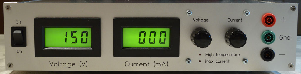
My brother has chosen LCD panelmeters with green backlight. On this picture the power supply is idling with 150V and 0mA.